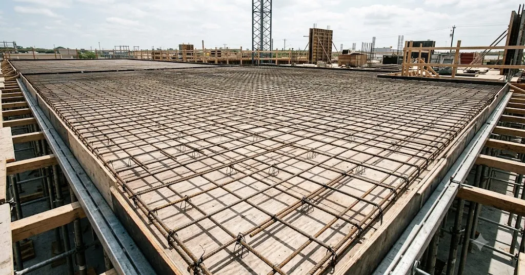
At Leeter, we have shipped wire, mesh, and rebar supports to contractors across North America and Europe since 2006. We do not detail your structures, but we see the downstream effect of good and bad drawing reading every day: it shows up in the accessory orders that land on our desk. This guide walks through the parts of a reinforcement drawing, how to interpret each callout, and how to convert what you see into a practical materials list.
What are reinforcement detailing drawings?
Reinforcement detailing drawings are the shop and field documents that translate a structural engineer's design into instructions a steel fixer can follow. They come in two main flavors. Placing drawings, sometimes called placing plans, show where each bar sits in the structure using plan and section views. Bar schedules, sometimes printed as a bar bending schedule, list every bar as a line item with its mark, size, length, shape, and quantity.
Think of the placing drawing as the map and the schedule as the parts list. The map shows a footing, a wall, or a slab with bars drawn in and labeled by mark. The parts list tells you how many of each mark to fabricate, how long to cut them, and what shape to bend them into. You rarely use one without the other. A fixer on site reads the placing drawing to know where bars go, then checks the schedule to confirm lengths and counts before cutting or ordering.
Most drawings follow a regional detailing standard. In North America that usually means ACI 315 conventions and the CRSI Manual of Standard Practice. In the UK and much of Europe it means BS 8666 shape codes. The logic is the same across standards even when the notation differs, so once you understand the structure of a drawing you can read most of them.
How do you read bar marks and a bar schedule?
A bar mark is a unique label that ties a bar on the drawing to a line on the schedule, so every piece of steel can be tracked from paper to placement. When you see something like "12" or "B03" next to a bar on a plan, that is the mark. Find the matching row on the schedule and you get the full specification.
A typical bar schedule row carries these fields, and reading them in order builds the whole picture:
- Bar mark: the unique reference, matched to the placing drawing.
- Number of bars: how many identical pieces to fabricate.
- Bar size: the diameter, given as an imperial bar number (#4, #5, #6) or a metric millimeter value (12, 16, 20).
- Length: the cut length of a single bar before or after bending, depending on the standard.
- Shape code and dimensions: the bend shape plus the A, B, C leg dimensions.
- Comments: notes on location, epoxy coating, or special handling.
Bar sizes deserve a quick note. A #4 bar is roughly 1/2 inch in diameter, a #5 is 5/8 inch, a #6 is 3/4 inch. The number is the diameter in eighths of an inch. Metric sizes state the diameter in millimeters directly, so a 16 bar is 16 mm. Getting the size wrong throws off both your bend allowances and your accessory counts, because heavier bars need sturdier chairs and more tie wire per crossing.
When you total a schedule, sum the bar counts by size to get piece counts, and multiply length by count and unit weight to get tonnage. That tonnage figure is what you order steel against. The piece and crossing counts are what you order accessories against, which we return to later.
What do shape codes and bending dimensions mean?
Shape codes are standardized numbers or diagrams that define how a straight bar is bent, and each code pairs with lettered dimensions that give the exact leg lengths. A straight bar is the simplest shape. From there you get L-bends, U-bars, closed stirrups, and hooked bars, each with its own code.
Under BS 8666, common codes include shape 00 for a straight bar, shape 21 for an L-shaped bar, and shape 60 for a closed link or stirrup. Under ACI and CRSI practice, shapes are often shown as small diagrams with dimensions rather than numbered codes, but the idea is identical: the drawing tells you the finished geometry. The lettered dimensions, usually A, B, C, and sometimes D and E, correspond to the legs of the bent bar as shown in the shape diagram.
Two details trip up newcomers. First, the total cut length is not always the sum of the leg dimensions, because bending steel around a pin changes the effective length. Detailing software and standards build in bend deductions and allowances, so trust the stated cut length on the schedule rather than adding legs yourself. Second, hooks matter. A standard hook adds a defined extension and a specific bend diameter that depends on bar size. Getting a hook length wrong can compromise anchorage, which is the whole reason the hook exists.
Stirrups and ties are their own category. These are the small closed or open shapes that wrap longitudinal bars in beams and columns. They control spacing, resist shear, and hold the cage square. The schedule tells you the stirrup shape, size, and spacing, and the placing drawing shows the zones where spacing tightens, often near supports and connections.
How are spacing and cover shown on drawings?
Spacing and cover are the two callouts that most directly affect how you place steel and where your chairs go, and both appear as short notations you learn to read at a glance. Spacing is the center-to-center distance between parallel bars. Cover is the clear distance between the outside face of the steel and the surface of the concrete.
Spacing usually appears as a note like "#5 @ 12 o.c." which means #5 bars at 12 inches on center. In metric it reads "16 @ 200" for 16 mm bars every 200 mm. Sometimes the drawing shows the bars with a dimension string; other times it simply labels a bar and gives the spacing note. Either way, the spacing drives your bar count across a given length. Divide the run by the spacing, add one bar, and you have the count for that direction.
Cover is often stated in a general note that applies to the whole element: "Clear cover: 50 mm to all bars" or "2 in. cover, top and bottom." Cover exists to protect steel from corrosion and fire, and it is one of the first things an inspector checks. This is where accessories come in directly. The height and type of chair or spacer you select is what physically holds the steel at the correct cover during the pour. If the drawing calls for 50 mm bottom cover, you need supports that set the mat exactly that far off the formwork.
Here is a quick reference for callouts you will see and what each one is telling you:
| Callout on drawing | What it means | What it affects |
|---|---|---|
| #5 @ 12 o.c. | #5 bars, 12 inches on center | Bar count and crossing count |
| 16 @ 200 | 16 mm bars every 200 mm | Bar count and crossing count |
| Clear cover 50 | 50 mm clear cover to bar face | Chair and spacer height |
| Shape 60 | Closed stirrup or link | Tie count, cage assembly |
| Lap 40d | Lap length of 40 bar diameters | Extra bar length, splice count |
| T&B | Top and bottom | Two mats, more chairs and ties |
| EW | Each way | Bars run in both directions |
Reading these in combination is the real skill. A slab note might read "#5 @ 12 EW, T&B, 2 in. cover." That single line tells you bars run each way, in both a top and bottom mat, spaced 12 inches, held 2 inches off each face. From it you can derive bar counts, crossing counts for tie wire, and the number and height of chairs and bolsters needed.
What are laps and splices on a schedule?
A lap, or lap splice, is the overlap between two bars that transfers force from one to the next where a single bar is not long enough to run the full length. The schedule and general notes tell you the required lap length, usually expressed as a multiple of bar diameter, such as 40d, meaning 40 times the diameter.
Laps matter for two reasons. They add steel, because every splice consumes extra bar length, and they add tie points, because lapped bars are usually wired together at the overlap. A run that needs three bars end to end has two laps, and each lap adds length and ties. When you estimate, account for laps or your steel tonnage and tie wire both come up short.
Splice locations are not arbitrary. Engineers specify where laps may fall, often away from points of maximum stress, and the placing drawing or notes will show staggered splice patterns so that not every bar splices at the same section. When you read a wall or column elevation, look for the splice zone callouts. They change your bar cut lengths and your tie counts in that region.
How do you turn a drawing into an accessory takeoff?
An accessory takeoff converts the bars shown on a drawing into the consumables that install and support them, mainly tie wire and bar supports, and you build it from the counts you already extracted. The drawing does not usually list accessories, so this step is on the estimator.
Start with tie wire. Every intersection where two bars cross and get tied is one tie. Count crossings from the spacing: a mat of bars at a given spacing in each direction produces a predictable grid of intersections. Not every crossing is tied on every job, common practice ties a percentage in a staggered pattern, but the crossing count is your baseline. Each tie consumes a short, repeatable length of rebar tie wire, so once you know ties per structure you can convert to coils or rolls. Add extra for laps, stirrups, and rework.
Next, bar supports. Cover callouts tell you the height, spacing rules and slab area tell you the quantity. A bottom mat sitting 2 inches off the form needs rebar chairs or bolsters of that height, spaced on a grid the engineer or contractor sets, often every few feet in each direction. Top mats in slabs need higher supports or upper continuous chairs to hold them down at the correct top cover. Beams and columns use different support types, but the logic holds: read the cover, pick the height, count by area or length.
A workable takeoff sequence looks like this:
- Total bars by mark and size from the schedule.
- Derive crossing counts from spacing notes for tie wire.
- Add lap and stirrup ties on top of mat crossings.
- Read cover callouts to set chair and spacer heights.
- Count supports by slab area or member length and spacing.
- Add a waste and contingency allowance for site conditions.
The honest truth is that no two crews tie at the same rate or space chairs identically, so a takeoff is an informed estimate, not a guarantee. Build in a sensible allowance. If you are unsure which support height or wire gauge suits your bar sizes and cover, that is exactly the kind of question we help contractors answer before they request a quote.
Frequently asked questions
What is the difference between a placing drawing and a bar schedule?
A placing drawing is the plan and section view showing where each bar sits in the structure, labeled by mark. A bar schedule is the tabular parts list giving each mark's size, length, shape, and quantity. You use the placing drawing to locate steel and the schedule to fabricate and count it. They are read together, not in isolation.
How do I know what bar size a callout refers to?
Bar size comes from the number in the callout. Imperial bars use a number in eighths of an inch, so #5 is 5/8 inch diameter. Metric bars state the diameter in millimeters, so 16 means 16 mm. The bar schedule lists the size in its own column, and the placing drawing repeats it in spacing notes like "#5 @ 12 o.c."
What does a shape code tell me?
A shape code defines how a straight bar is bent into its finished geometry, paired with lettered leg dimensions. Standards like BS 8666 use numbered codes such as 00 for straight and 60 for a closed link. ACI and CRSI drawings often use small shape diagrams instead. Always use the stated cut length rather than adding the leg dimensions yourself, because bending changes effective length.
How do I estimate tie wire from a drawing?
Estimate tie wire by counting bar crossings. Read the spacing in each direction, calculate the grid of intersections over the area, and treat each tied crossing as one tie of a repeatable wire length. Add ties for laps and stirrups. Crews rarely tie every crossing, so apply a realistic tie rate and a waste allowance to reach coil quantities.
How do cover callouts affect my accessory order?
Cover callouts set the height of your chairs and spacers. If the drawing specifies 2 inches of bottom cover, your supports must hold the mat exactly 2 inches off the formwork. Top mats need supports sized for top cover. Read every cover note per element, because footings, slabs, and walls often specify different values, and pick support heights to match each.
Reading reinforcement drawings well pays off long before the concrete arrives. Once you can move from bar marks to schedules to spacing and cover, the accessory takeoff falls into place, and you order the right tie wire and supports the first time. If you want a second set of eyes on wire gauge, chair height, or coil quantities for your next pour, contact our team and we will help you match the accessories to your drawings.
